


A generator running but not producing stable voltage most often points to the automatic voltage regulator — but a bad exciter winding, shorted rectifier diode, or loose sensing wire can mimic AVR failure. Before ordering a replacement, run the systematic test process below. It applies to any qualified technician or maintenance professional working with standard test equipment on residential or commercial gensets.
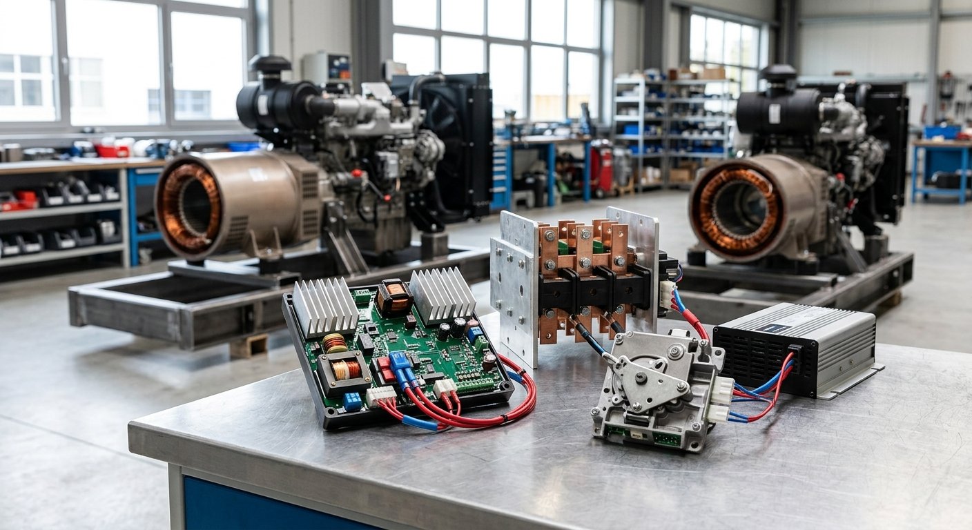
The automatic voltage regulator is a small but critical control device. It monitors the generator’s output voltage through a sensing circuit, then adjusts DC excitation current to the exciter field to keep output stable — typically within ±1–2% of the rated voltage. On a 120/240V single-phase residential unit or a 480V three-phase commercial genset, that stability is what protects connected loads from over- or under-voltage damage.
When the AVR fails, the generator either puts out no voltage, excessive voltage, or erratic voltage that hunts and surges. Understanding which symptom you’re seeing narrows down where the fault lives before you ever pull out a meter.
Each of these symptoms points to specific tests. Work through them in order before condemning the AVR.
A bad AVR is common, but so is a bad exciter winding, a shorted diode on the rectifier bridge, or a loose sensing wire that mimics AVR failure.
You are working near rotating equipment and live electrical terminals. Confirm all safety lockouts, PPE, and local electrical safety standards apply before beginning. OSHA’s electrical safety standards for general industry (29 CFR 1910 Subpart S) cover the baseline requirements for this type of work.
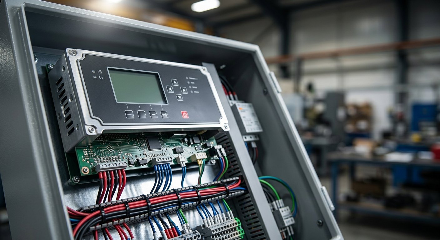
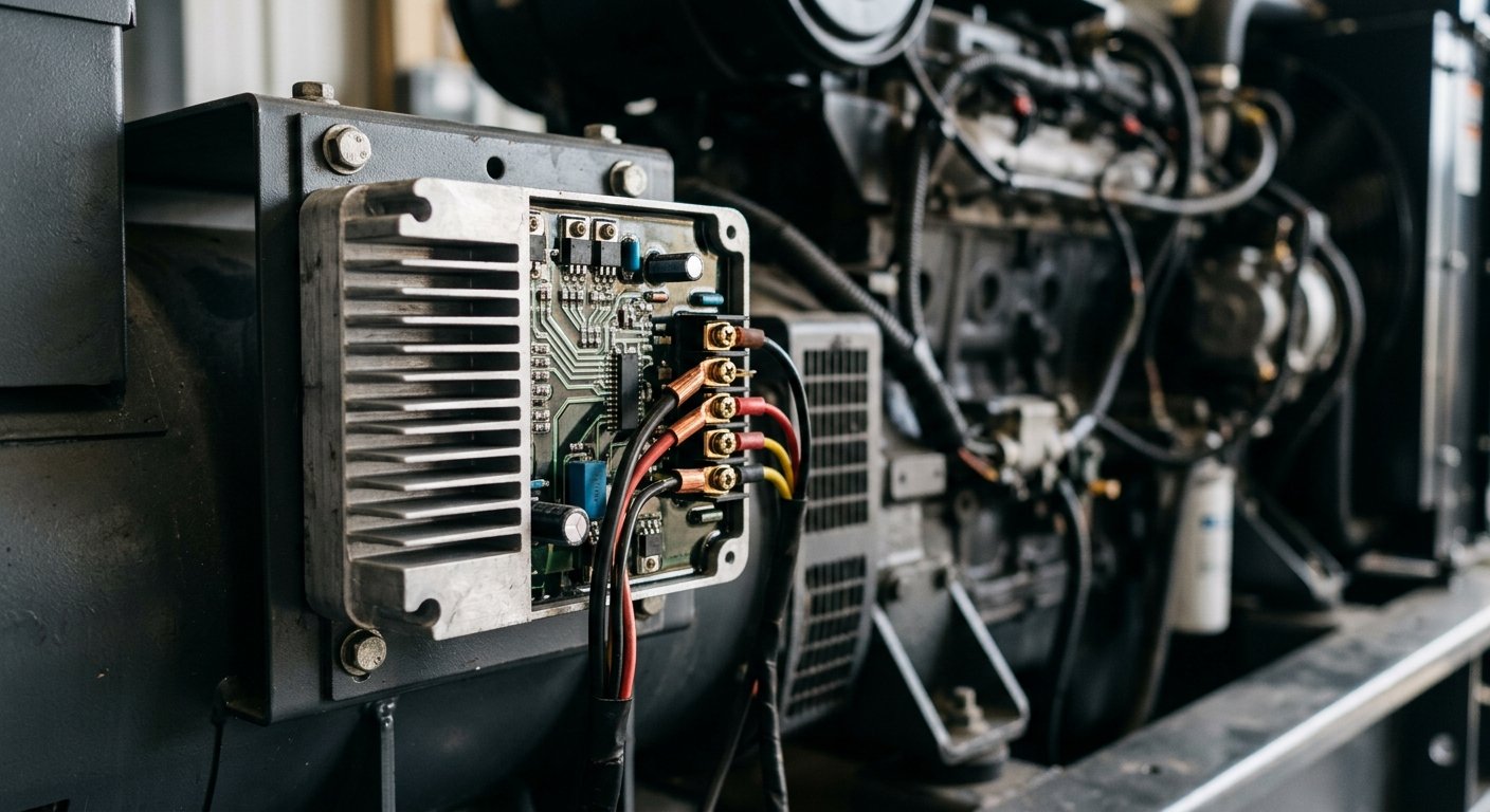
Before touching a meter, look at the AVR and its connections. Check for burnt or discolored components on the AVR board, loose or corroded terminals, damaged sensing wires (often thin gauge, routed from the stator), and evidence of moisture intrusion or carbon tracking. A visually burnt AVR is a failed AVR — skip to replacement. If it looks intact, continue testing.
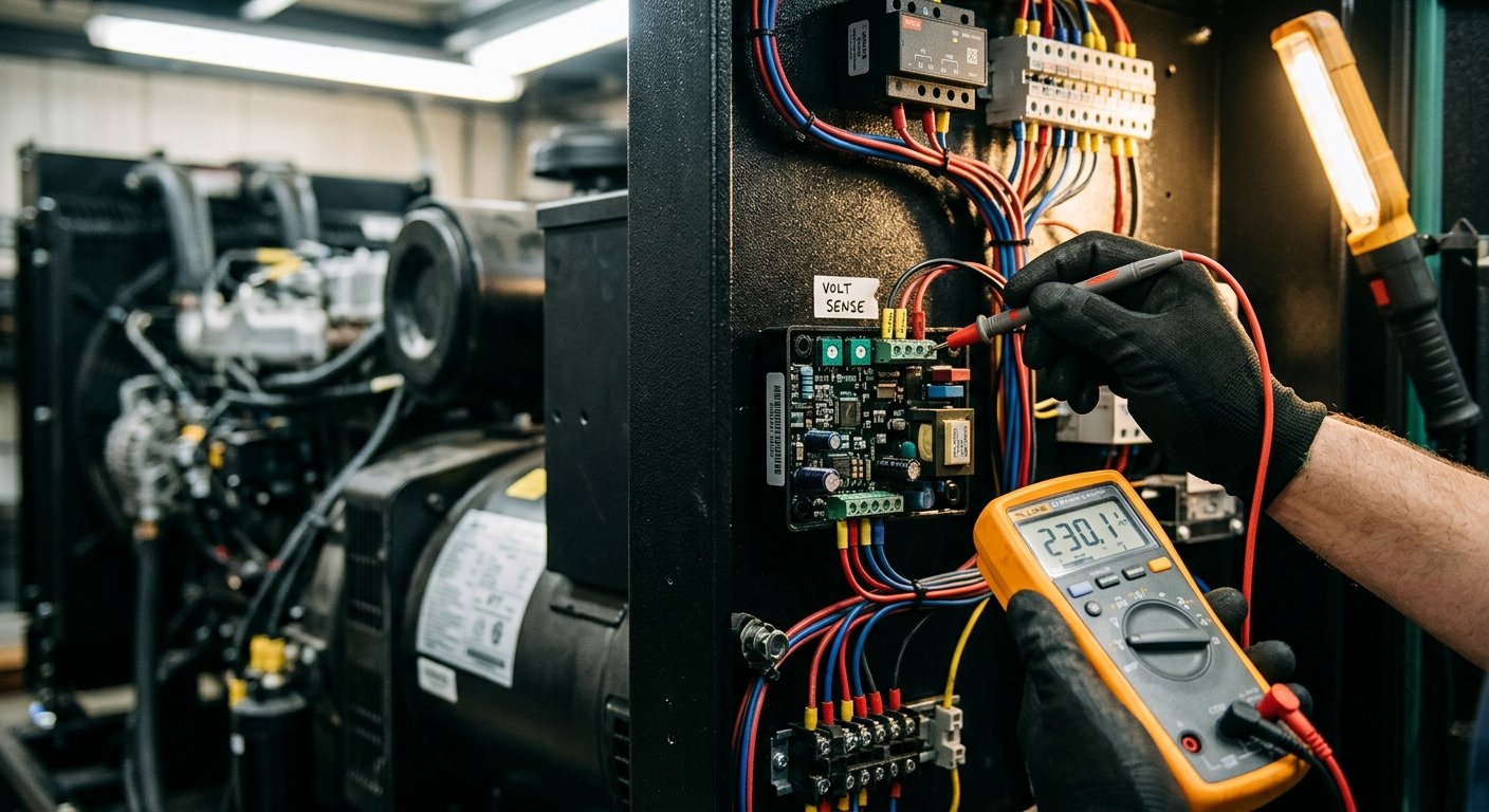
With the generator running at no load and output breaker open, measure AC voltage at the AVR sensing terminals (typically labeled P1/P2, S1/S2, or similar). The sensing input should be in the range specified by the AVR manufacturer — commonly 95–130VAC or 190–260VAC depending on the model. Zero volts at the sensing terminals indicates a wiring or auxiliary winding issue, not necessarily an AVR problem.
With the generator running, measure DC voltage at the AVR output terminals feeding the exciter field winding (F+ and F-). At no load, expect 10–50VDC depending on design. Zero VDC output means the AVR is not firing — suspect internal failure or missing sensing input. Full voltage with low generator output shifts suspicion to the exciter windings and rotating rectifiers.
Shut down the generator and isolate the exciter field terminals. Measure resistance across F+ and F- — typically a few ohms to around 30 ohms per your service manual. An open reading (OL) means the field winding is burnt; a reading far below spec suggests a shorted winding. Either condition will cause the AVR to behave abnormally even if it is otherwise functional.
With the generator stopped and rotor accessible, use your DMM in diode test mode. Each diode should show a forward voltage drop of approximately 0.4–0.7V and open (OL) in reverse. Near-zero in both directions means shorted; OL in both directions means open. The IEEE recommends replacing rotating rectifiers as a set rather than individually to avoid asymmetric performance.
Most AVRs have a voltage adjustment potentiometer — often labeled VOLT or V-ADJ. If output is stable but 5–10% high or low, make small trimmer adjustments while monitoring output. If voltage hunts after adjustment, also check the stability (STAB) trimmer — small clockwise adjustments typically slow the response and reduce hunting. If voltage cannot be brought into range and all winding checks pass, the AVR is faulty.
Knowing where the fault actually lives prevents ordering the wrong part. The table below maps each condition to the most likely failed component.
| Condition found during testing | Replace / investigate AVR | Look elsewhere first |
|---|---|---|
| Visible burn damage on AVR board | Yes — replace AVR | — |
| DC output confirmed zero, sensing input present | Yes — internal AVR failure | — |
| Voltage won’t stabilize; windings test good | Yes — AVR faulty | — |
| Sensing voltage absent at AVR terminals | — | Auxiliary winding or wiring |
| Exciter field winding open or shorted | — | Exciter field winding |
| Rectifier diode reads near-zero or OL both ways | — | Rotating rectifier assembly |
| Main stator insulation broken down | — | Main stator winding |
MTS Power Products carries a wide range of AVRs and automatic voltage regulators compatible with major generator brands. As a manufacturer-direct supplier, the team can help you cross-reference your existing AVR by manufacturer and part number — call 305-634-1511 or use the contact form if you’re unsure which unit fits your genset. That kind of one-on-one support is something you simply won’t get from a big-box distributor.
Generators in humid coastal environments — like South Florida — benefit from periodic inspection and protective measures to extend component life. The U.S. Department of Energy recommends regular generator maintenance as part of any home or facility energy resilience plan.
If you’re building out or troubleshooting a broader backup power system, the full generator parts catalog covers everything from transfer switches to governors and battery chargers.
The clearest indicators are no output voltage, unstable or hunting voltage, or voltage that runs significantly high or low and cannot be corrected by trimmer adjustment. Confirm with the step-by-step test process above — rule out winding faults and rectifier failures first before condemning the AVR.
You can perform resistance checks on the AVR’s external connections and on the exciter field winding with the generator stopped. However, to verify DC output and sensing input under real conditions, the generator must be running. A bench test of the AVR in isolation is not reliable without specialized test equipment.
DC output from the AVR to the exciter field varies by design — commonly 10–50VDC at no load, increasing under load as the AVR commands more excitation. Always reference the specific service manual for your generator model. Generic range estimates are a starting point, not a substitute for the manufacturer’s specification.
Under normal operating conditions with proper maintenance, an AVR can last many years. Exposure to moisture, heat, voltage spikes, or sustained overload conditions shortens service life significantly. Generators in humid coastal environments — like South Florida — benefit from periodic inspection and protective measures to extend component life. The U.S. Department of Energy recommends regular generator maintenance as part of any home or facility energy resilience plan.
For qualified technicians and experienced maintenance personnel, yes — with proper PPE and a calibrated meter connected to the output. Make small adjustments and allow the voltage to stabilize before moving further. If you’re not confident working near live generator terminals, have a licensed electrician perform the adjustment. Overvoltage from incorrect trimmer settings can damage connected equipment.
The MTS Power Products team in Miami works directly with technicians and facility managers nationwide — with technical support to match every part they supply.
MTS Power Products is a Miami-based, manufacturer-direct supplier of generator parts — including AVRs, transfer switches, battery chargers, and governors — serving commercial, marine, and residential backup power needs nationwide. They combine deep technical expertise with personalized service, helping generator technicians, electricians, facility managers, marine operators, and homeowners select the right parts and keep their backup power systems running reliably. Their direct-from-manufacturer model delivers fair pricing and knowledgeable support that big-box distributors cannot match. Visit mtspowerproducts.com →