


A 3-phase automatic transfer switch monitors incoming utility power on all three phases simultaneously, detects a fault or outage, and switches a connected load to a standby generator — typically within 10 to 30 seconds — without manual intervention. It’s the critical link between a generator and any facility running three-phase equipment: motors, HVAC compressors, data center PDUs, and commercial lighting panels.
Single-phase transfer switches are simpler: one hot leg, one neutral, one decision. Three-phase power runs on three separate conductors, each carrying current 120 electrical degrees out of phase with the others. Industrial motors, elevators, and large HVAC systems depend on this phase relationship to run efficiently. Drop one leg, and a three-phase motor doesn’t just lose a third of its power — it can stall, overheat, or run backwards.
That’s why a 3-phase automatic transfer switch monitors all three phases independently. Lose phase B while A and C look fine? The ATS catches it. Voltage sag on one leg? It catches that too. This multi-phase monitoring is the core reason three-phase ATS units are more complex — and more critical — than their single-phase counterparts.
Phase imbalance — where one leg runs more than 2–3% lower than the others — can be just as damaging as a total outage for three-phase motors. A quality ATS controller will flag imbalance as a transfer trigger, not just total loss of power.
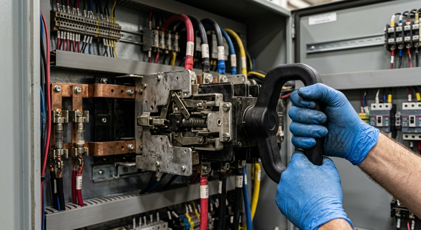
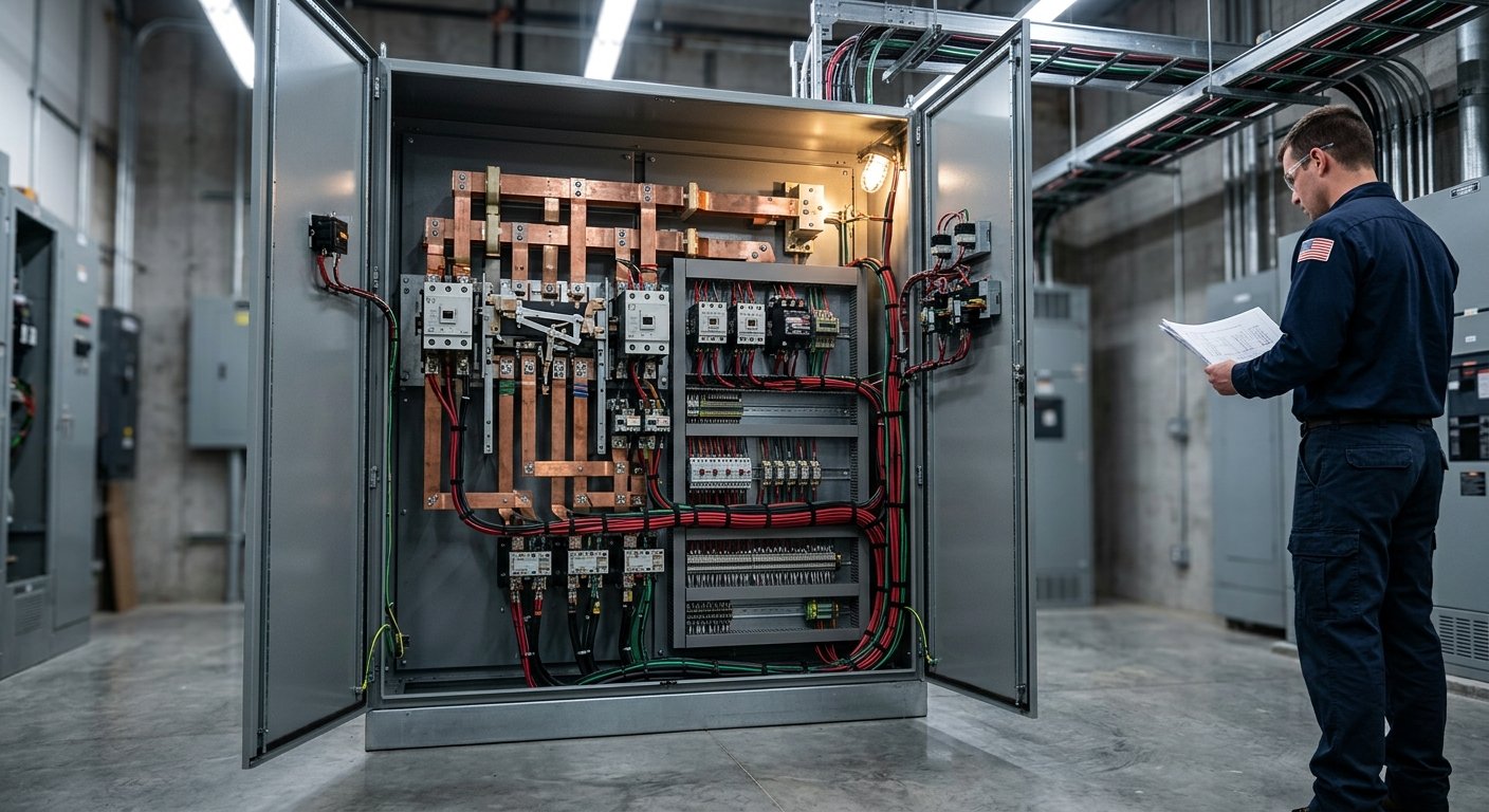
This is the physical switching element — either a contactor-based or circuit-breaker-based design. In an open-transition (break-before-make) unit, utility and generator power are never connected simultaneously. The load sees a brief interruption — typically under 100 milliseconds for the actual switch throw, but the full transfer time includes the generator startup sequence. Closed-transition (make-before-break) units overlap the two sources momentarily for zero interruption, but they require precise synchronization of voltage, frequency, and phase angle before the overlap occurs.
The ATS controller is the intelligence layer. It reads voltage and frequency from both the utility side and the generator side, runs the decision logic, and sends control signals to both the transfer mechanism and the generator. Modern controllers include programmable time delays — a short delay before transferring to generator (to filter out momentary sags) and a longer delay before transferring back to utility (to confirm utility has truly stabilized).
Higher-end controllers add RS-485 or Ethernet communications for remote monitoring, event logging, and integration with building management systems. If you’re managing a facility with a critical load, that data visibility isn’t a luxury — it’s how you prove your system performed correctly after an outage.
Each of the three phases is continuously sampled. The controller compares measured voltage against a configurable pickup/dropout window — commonly 90–95% of nominal for dropout and 95–100% for pickup on the utility return. Frequency sensing typically flags anything outside 58–62 Hz on a 60 Hz system. Both thresholds matter: a generator that’s running but producing unstable output should not be accepted as a valid source.
The ATS controller senses undervoltage, overvoltage, phase loss, or frequency deviation on one or more phases. A short programmable delay (typically 1–3 seconds) filters transient sags before committing to transfer.
The controller sends a dry-contact start signal to the generator’s engine controller. The engine cranks, fires, and accelerates to governed speed — usually reaching stable output within 10–20 seconds depending on engine size and temperature.
The ATS controller verifies that generator voltage (on all three phases) and frequency are within acceptable limits before allowing the transfer to proceed. This prevents connecting a load to an unstable source.
The transfer mechanism opens the utility contactor and closes the generator contactor (open-transition) or synchronizes and overlaps briefly (closed-transition). The facility load is now running on generator power.
When utility voltage returns and stabilizes, the controller waits through a configurable return delay (often 5–30 minutes) before switching back. This prevents repeated cycling if utility is unstable. The generator then runs unloaded briefly before shutdown.
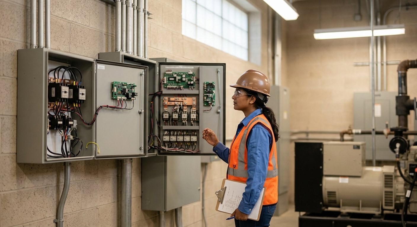
Most commercial and industrial installations use open-transition ATS units. They’re simpler, less expensive, and perfectly adequate for most loads — including HVAC systems, lighting, and general power. The brief interruption during transfer (the generator startup time) is acceptable when the alternative is a prolonged outage.
Closed-transition units are appropriate when the load cannot tolerate even a momentary interruption: hospital operating rooms, certain data center applications, broadcast facilities, or precision manufacturing equipment. The trade-off is cost and complexity — the synchronization requirement means the ATS controller must verify phase angle match between utility and generator before closing both contactors simultaneously. According to NFPA 110, the Standard for Emergency and Standby Power Systems, different emergency system classifications carry specific requirements for transfer times and equipment ratings that should govern your selection.
| Feature | Open Transition | Closed Transition |
|---|---|---|
| Transfer interruption | Brief (gen startup time) | Near-zero overlap |
| Synchronization required | No | Yes |
| Typical applications | Commercial, industrial, HVAC | Hospitals, data centers, broadcast |
| Controller complexity | Moderate | High |
| Installation cost | Lower | Higher |
Undersizing an ATS is one of the most common field mistakes. The transfer switch must be rated for the full continuous current of the load it serves — not just the generator’s output rating. A 150 kW generator at 480V three-phase delivers approximately 180 amps per phase (P = √3 × V × I × PF). Your ATS must be rated at or above that continuous current, with appropriate interrupting capacity for fault conditions.
Motor-heavy loads add a wrinkle: motors draw 5–7 times their running current during startup (locked-rotor amperage). The ATS doesn’t interrupt this surge — it just needs to handle it thermally and mechanically. Look for switch ratings that include both continuous and withstand ratings. The IEEE C37.96 guide for AC motor protection provides useful background on motor starting characteristics that affect ATS sizing decisions.
Never size an ATS solely based on the generator nameplate. Size it for the actual connected load plus a reasonable growth margin. An ATS that’s thermally stressed on every transfer will fail prematurely — usually at the worst possible moment.
An automatic transfer switch that hasn’t been exercised is an unknown. Monthly exercise cycles — where the ATS actually transfers load to the generator, not just idles the engine — are standard practice under NFPA 110 for critical facilities. During those cycles, verify that all three phases transfer cleanly, that the ATS controller logs the event without errors, and that retransfer back to utility completes normally.
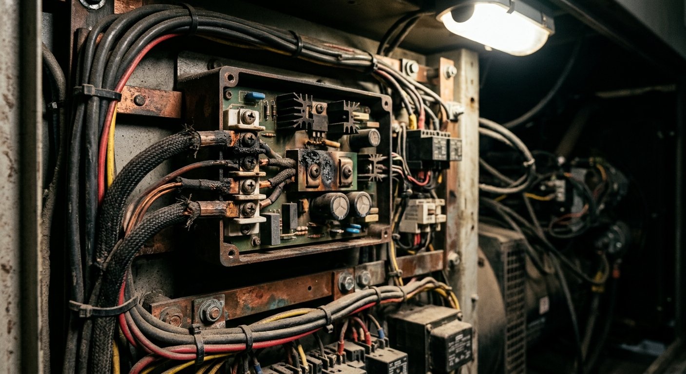
Physically inspect contactor contacts annually for pitting or carbon buildup, check control wiring terminals for corrosion (especially in coastal environments like South Florida, where salt air accelerates oxidation), and verify that the exerciser clock and time delays are still configured correctly after any power interruption to the controller itself.
When an ATS fails — and eventually, all mechanical switching devices do — having the right replacement parts ready matters. MTS Power Products supplies transfer switches direct from the manufacturer, covering both residential and commercial three-phase applications. If your ATS controller is hunting or throwing spurious transfer events, the issue is often the sensing circuit or the control board — not the switch mechanism itself. That’s also where automatic voltage regulators on the generator side come into the picture: an AVR that’s not holding output voltage tight will trigger nuisance transfers.
A transfer switch that hasn’t been exercised under load is not a standby system — it’s a liability with a nameplate.
Standby battery chargers also play a role in ATS reliability. Many ATS controllers and the generator’s engine control module draw from a standby battery. A weak or sulfated battery means the generator may not crank when the ATS sends the start signal. Keeping that battery on a quality float charger is inexpensive insurance — MTS carries battery chargers suited for generator standby applications.
The U.S. Department of Energy’s Operations and Maintenance Best Practices Guide reinforces that documented, scheduled maintenance on standby power equipment — including transfer switches — is the single greatest factor in system reliability when called upon.
Total transfer time — from utility fault detection to load running on generator — is typically 10 to 30 seconds. The switch throw itself takes milliseconds; most of that time is the engine starting and the ATS controller confirming stable generator output before allowing the transfer. Closed-transition units can overlap utility and generator for near-zero interruption, but require synchronized voltage and frequency.
The ATS controller is the electronic brain — it monitors voltage and frequency, runs transfer logic, and sends control signals. The transfer switch is the physical mechanism (contactors or breakers) that actually moves the load between sources. They work together as a system, but they’re distinct components that can sometimes be serviced or replaced independently.
Rarely. Most residential services in the US are single-phase 120/240V. Three-phase ATS units are sized and priced for commercial and industrial loads. If a home has a three-phase service (uncommon, but it happens with large workshops or agricultural properties), a properly rated three-phase transfer switch is required — using a single-phase unit on a three-phase service would leave loads on two phases unprotected.
The most common causes are overly sensitive voltage dropout settings, a faulty sensing board, loose connections on the utility sensing wiring, or an AVR on the generator that isn’t holding output voltage within the ATS’s pickup window. Nuisance transfers are disruptive and stressful on equipment — diagnose the root cause rather than simply raising the dropout threshold.
NFPA 110 recommends monthly exercise under load for emergency standby systems. At minimum, the ATS should actually transfer the load — not just idle the generator. Annual inspections should include physical inspection of contacts, control wiring, and battery condition. Log every transfer event, whether scheduled or unplanned, to build a maintenance history.
MTS Power Products ships transfer switches, AVRs, battery chargers, and governor components direct from the manufacturer — with real technical support from our Miami-based team.
MTS Power Products is a Miami-based, manufacturer-direct supplier of generator parts — including AVRs, transfer switches, battery chargers, and governors — serving commercial, marine, and residential backup power needs nationwide. They combine deep technical expertise with personalized service, helping generator technicians, electricians, facility managers, marine operators, and homeowners select the right parts and keep their backup power systems running reliably. Their direct-from-manufacturer model delivers fair pricing and knowledgeable support that big-box distributors cannot match. Visit mtspowerproducts.com →