


A generator that surges, hunts, or runs at the wrong frequency isn’t just an annoyance — it’s a liability. Sensitive equipment gets damaged. Alarms trip. Loads drop offline. In most cases, the root cause comes back to one component: the governor. Understanding how to perform a proper generator governor adjustment can be the difference between a genset that runs rock-solid at 60 Hz and one that constantly chases its own tail.
This guide walks through the practical process of diagnosing governor issues, adjusting mechanical and electronic governors, and verifying correct operation. Whether you’re tuning a standby unit at a commercial facility, maintaining a marine generator, or working on a fleet diesel at a job site, the fundamentals are the same.
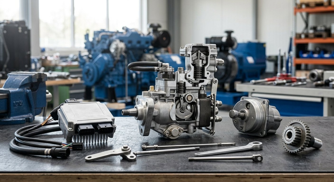
The governor is the speed control system of your generator. Its job is to maintain a constant engine RPM under varying load conditions. On a 60 Hz system, that means holding the engine at 1800 RPM (for a 4-pole generator). When you add load, the engine wants to slow down. The governor detects that drop and opens the fuel rack or throttle to compensate. When load drops, it reduces fuel input to prevent overspeed.
A governor that’s out of adjustment — or failing — causes generator frequency instability, visible as a fluctuating Hz reading on your panel meter. This condition is sometimes called governor hunting, where the engine RPM oscillates continuously because the governor is overcorrecting in both directions.
According to the National Electrical Manufacturers Association (NEMA), generator frequency should remain within ±5% of nominal under steady-state conditions, and far tighter tolerances apply in healthcare, data center, and life-safety applications.
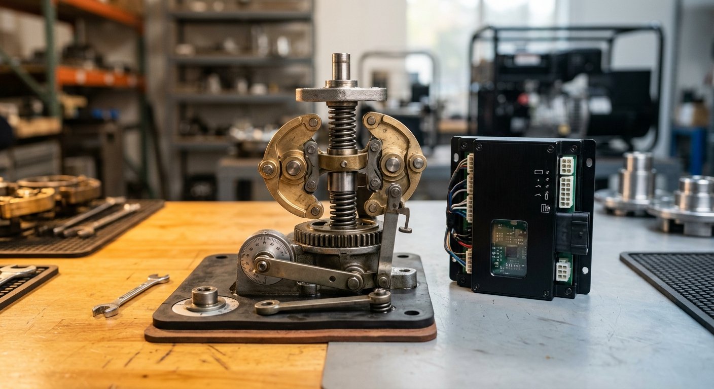
Found on older and smaller gensets, mechanical governors use flyweights, springs, and linkages to sense engine speed and actuate the fuel control mechanically. They’re reliable but require periodic physical adjustment — spring tension, droop settings, and linkage geometry all affect performance.
Modern and larger gensets use an electronic governor system, typically consisting of a magnetic pickup (MPU) sensor on the flywheel ring gear, a governor controller or amplifier board, and an electromechanical actuator that drives the fuel rack. Electronic governors offer faster response, tighter frequency regulation, and adjustable gain and stability parameters — but they also fail in ways mechanical governors don’t, including MPU signal loss and actuator coil burnout.
MTS Power Products carries governors and actuator components for a wide range of genset applications. If you need a replacement governor for your generator, the team in Miami can help you identify the correct unit before you order — call 305-634-1511.
Don’t touch the adjustment screws until you’ve confirmed the governor is actually the issue. Many frequency instability complaints trace back to other root causes:
Before proceeding, connect a calibrated tachometer or use your panel’s Hz meter as a proxy (60 Hz = 1800 RPM on a 4-pole unit). Record baseline behavior: Does the hunting occur at no-load, full-load, or only during load transitions?
Run the generator at no-load for 10–15 minutes. Governor behavior changes significantly between cold and operating temperature. Adjusting a cold engine produces inaccurate results. Confirm coolant temperature is in the normal operating range before proceeding.
Locate the speed adjustment screw or potentiometer on the governor controller. On mechanical governors, this is typically a threaded set screw with a locknut. On electronic governors, it’s a trim pot on the control board or an external speed pot.
With the generator running at no-load, adjust speed until your tachometer reads 1800 RPM (or 1500 RPM on 50 Hz systems). On most electronic governor controllers, clockwise rotation increases speed; counterclockwise decreases it. Make small adjustments — quarter turns at a time — and allow the engine 5–10 seconds to stabilize between each change.
The gain control determines how aggressively the governor responds to speed deviations. Too much gain causes governor hunting — the system overcorrects and oscillates. Too little gain results in sluggish speed recovery when load is applied.
If the engine is hunting at no-load, reduce gain in small increments until oscillation stops. If the engine bogs down and recovers slowly under load, increase gain slightly. This is an iterative process — patience and small adjustments win here.
Many electronic governor controllers have a separate stability or damping potentiometer. This setting controls how quickly the governor’s response damps out after a correction. Low stability causes ringing (continued oscillation after a load change). High stability causes sluggishness.
Apply and remove a known load block — ideally 25–50% of rated kW — and watch the frequency recovery on your meter. Target: frequency should return to 60 Hz within 1–2 seconds without oscillating more than once. Adjust the stability pot until this behavior is achieved.
Droop is intentional speed reduction under load — typically 3–5% for most standalone gensets. It allows parallel generators to share load proportionally. If you’re running a single genset, droop can be set near zero (isochronous mode) for tightest frequency regulation. If you’re paralleling generators, match droop settings across all units. Mismatched droop is a common cause of circulating current and instability in parallel systems.
Apply full rated load and confirm frequency stays within ±2 Hz of nominal (ideally tighter). Check that voltage simultaneously remains stable — if voltage fluctuates with frequency changes, the automatic voltage regulator (AVR) may also need attention. Governor and AVR tuning are related; instability in one system can mask or amplify problems in the other.
Once stable operation is confirmed, secure all locknuts on mechanical governors. Document the final pot positions or settings on electronic controllers — photograph the board if needed. Log the adjustment date, load conditions during testing, and final Hz/RPM readings. This baseline is invaluable for the next service interval.
If you’ve gone through the full adjustment process and still can’t achieve stable frequency, the governor component itself may need replacement. Common failure points include:
For marine generator applications in particular, salt air accelerates corrosion on control boards and actuator connectors. The marine electronics industry has documented how connector corrosion accounts for a high percentage of electronic control failures in saltwater environments — the same applies to genset governors aboard vessels.
MTS Power Products supplies replacement governor components direct from manufacturers, covering a broad range of commercial, industrial, and marine generator applications. Reach the Miami team at 305-634-1511 to verify compatibility before ordering.
For South Florida homeowners and facility managers, a generator that hunts or surges is a problem that typically surfaces at the worst possible moment — the first time the grid goes down during hurricane season. An annual generator governor check before June 1st (the start of Atlantic hurricane season, per the National Weather Service Miami) is straightforward maintenance that pays off when you need the machine most.
If your standby generator exercises monthly (as it should), watch the frequency meter during that run. Consistent Hz between 59.5 and 60.5 Hz at no-load is a healthy sign. Anything outside 58–62 Hz warrants investigation before storm season arrives.
Governor hunting — rhythmic RPM and frequency oscillation — is most commonly caused by excessive gain settings on the governor controller, a weak or intermittent magnetic pickup (MPU) signal, air in the fuel system, binding throttle linkage, or a failing actuator. Diagnose the mechanical and fuel systems before adjusting gain settings.
If the generator ran stably before and has gradually developed hunting or frequency drift, adjustment is the right first step. If adjustment brings no improvement, check the MPU output voltage and actuator coil resistance. Out-of-spec readings point to component replacement, not further tuning.
A standard 4-pole generator operating on a 60 Hz system should run at 1800 RPM. A 2-pole generator achieves 60 Hz at 3600 RPM. Always verify your generator’s pole count before setting speed — running a 4-pole unit at 3600 RPM will cause serious damage.
Yes, for most adjustments. You need a calibrated tachometer or reliable Hz meter, a small screwdriver for trim pots, and a load bank or known resistive load for testing. What you should not do is estimate or skip load testing — confirm stable operation under real load conditions before considering the job complete.
MTS Power Products supplies governor components direct from manufacturers for a wide range of genset brands and applications across the US. Contact the Miami team at 305-634-1511 or visit the generator parts store to find the right component for your application.
Need a governor, actuator, or MPU for your genset? MTS Power Products is a manufacturer-direct supplier based in Miami, serving generator technicians, facility maintenance teams, and marine operators nationwide. We carry the parts you need and the technical knowledge to help you select the right one. Call us at 305-634-1511 or browse our generator parts inventory to get started.