


Every year, millions of Americans lose utility power — some for hours, others for days or weeks. If you’re wiring a transfer switch for the first time, or troubleshooting one that isn’t performing reliably, getting the fundamentals right isn’t optional. A miswired transfer switch can backfire-feed the utility grid, create lethal voltage on lines where lineworkers are working, or simply fail to transfer when you need it most. This guide walks through generator transfer switch wiring the right way — practical, sequenced, and grounded in how these systems actually work in the field.
A transfer switch is the disconnect and switching mechanism that separates your generator from the utility grid, connects your loads to generator power, and — when utility power returns — safely reconnects those loads to the grid. It’s not optional. The Occupational Safety and Health Administration (OSHA) and the National Electrical Code (NEC) both require transfer switches for any generator connected to a building’s electrical system. Backfeeding utility lines is a real and documented cause of electrocution deaths among lineworkers.
Transfer switches come in two primary types:
For standby applications — hospitals, data centers, residential backup, or any critical facility — an automatic transfer switch is the standard. You can explore the full range of transfer switches at MTS Power Products to match your application.
Understanding the mechanism makes wiring it correctly far more intuitive. An automatic transfer switch continuously monitors the utility feed — typically watching for voltage dropout below a set threshold (commonly 80–85% of nominal voltage) for a defined time delay (often 1–10 seconds). When that threshold is crossed:
Closed-transition ATSs perform the transfer with momentary paralleling — there’s no power interruption at all, which matters for sensitive electronic equipment and server loads. Transfer time specs matter: a 200 amp automatic transfer switch rated for 10-cycle transfer (<100ms) is the minimum for most UPS-bypass commercial applications. According to NFPA 110, Level 1 systems — those serving life-safety loads — must restore power within 10 seconds of failure.
Before touching any wiring, gather what you need and establish safe working conditions. You’re dealing with 120/240V single-phase or 208/480V three-phase circuits. Mistakes are not self-correcting.
Critical safety rule: Verify utility power is fully de-energized at the main breaker before opening any panel. Test — don’t assume. Tag and lock out the main breaker per LOTO (Lockout/Tagout) procedures before beginning work.
Calculate the total connected load you need to power. For whole-home or whole-facility coverage, size the ATS to your main panel ampacity — typically a 200 amp automatic transfer switch for residential and light commercial. For critical-load-only panels (a subset of circuits), you may size down, but list every circuit and its amperage draw before deciding. Single-phase 120/240V is standard for residential; three-phase 208V or 480V is standard for commercial and industrial.
Match the ATS to your generator output specs: voltage, phase, and amperage must align. A 20kW residential generator at 240V single-phase produces roughly 83 amps at full load — that’s well within a 200A ATS, giving you headroom. A 100kW three-phase commercial genset at 480V produces approximately 120 amps per phase — verify your ATS ampacity per-phase rating accordingly.
The ATS mounts between the utility service entrance and your load panel. It needs to be accessible, protected from weather (or installed in a weatherproof enclosure if outdoor), and code-compliant in terms of clearance. Many 200A residential ATSs are designed for side-by-side mounting next to the main panel or as an all-in-one unit that replaces it.
With the utility main breaker locked out and confirmed de-energized, route the utility service conductors into the “Line” or “Normal” terminals of the ATS. In a typical 200A single-phase install, this is a 2-wire plus neutral and ground (2/0 or 3/0 AWG copper, depending on your service). Torque all terminals to manufacturer specification — loose connections generate heat and arc faults over time.
Connect the generator’s output conductors to the “Generator” or “Emergency” terminals of the ATS. Conduit from the generator’s output terminals (or output breaker) to the ATS. Keep generator and utility conductors separated throughout their run — this is both a code requirement and a practical reliability measure. For a transfer switch for generator use outdoors, use liquid-tight flexible conduit at the generator connection point to allow for vibration and thermal movement.
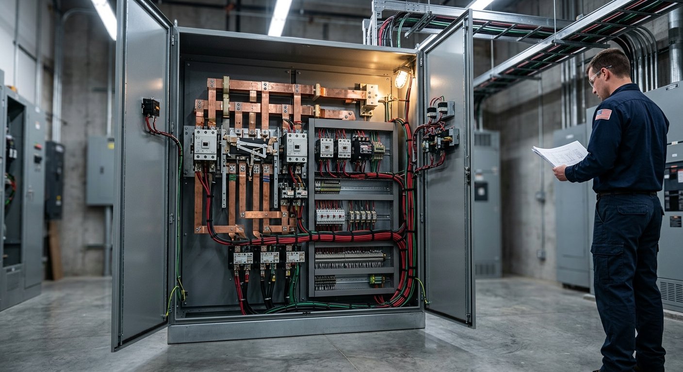
The “Load” terminals of the ATS connect to your load panel’s main lugs or main breaker. This is where the switched power — either utility or generator — flows to feed your circuits. Confirm polarity on single-phase systems and phase rotation on three-phase systems (incorrect rotation runs motors backwards).
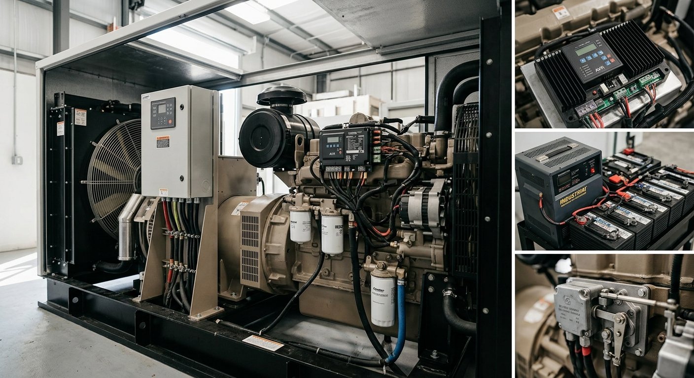
This is the communication link between the ATS and the generator’s start circuit. Most modern gensets use a simple two-wire start signal: when the ATS drops to close the start relay, it sends a crank signal to the generator’s control board. Some systems use a more complex multi-conductor harness for status signals, pre-alarm monitoring, or remote annunciation. Refer to both the ATS wiring diagram and the generator’s controller manual — mismatching this interface is one of the most common commissioning errors.
Neutral-to-ground bonding belongs at one point only — typically the utility service entrance. If your ATS switches the neutral (4-pole ATS), the generator’s neutral should be floating (unbonded at the genset). If your ATS is 3-pole (switches only the hot conductors), the generator neutral bonds to ground at the generator frame. Getting this wrong creates ground loops, nuisance GFCI trips, and potential shock hazards.
Before restoring utility power, verify all torque connections, continuity of each conductor, and correct terminal placement. Once utility is restored, test the ATS by simulating a utility outage (using the ATS test function or by opening the main breaker). The generator should start, reach stable output, and transfer. Time it. Retransfer to utility and verify cool-down. Log everything.
In most jurisdictions, permit and inspection requirements apply to any transfer switch installation, and many localities require a licensed electrician for utility-side work. Even if DIY is legally permitted, utility-side conductors carry lethal voltage — if you’re not trained and properly equipped, hire a licensed electrician. What a homeowner can typically do: understand the system, verify the work, and select the right equipment.
For a full home with a 200-amp main panel, a 200 amp automatic transfer switch is the standard match. If you’re powering only critical circuits, you can install a smaller manual or automatic transfer switch on a dedicated subpanel. Always calculate your actual load before selecting switch ampacity — don’t default to minimum ratings.
If the generator fails to start within the programmed crank timeout (typically three attempts over 45–90 seconds), most ATSs will alarm but remain in the “utility loss” state. Load stays de-energized. The ATS won’t re-close to a dead utility, and it won’t close to an absent generator signal. Regular monthly exercise runs and routine maintenance prevent this failure mode.
A 3-pole ATS switches only the three phase conductors (or two hots in single-phase), leaving the neutral continuous. A 4-pole ATS switches all conductors including the neutral, which is required when the generator has its own neutral-to-ground bond. Code and application drive the choice — consult NEC 250.20 and your ATS manufacturer’s guidance for your specific installation.
NFPA 110 recommends monthly no-load exercise tests and annual loaded tests for Level 1 and Level 2 systems. Contacts and control relays inside an ATS have finite cycle life — periodic inspection by a qualified technician catches worn contacts, corroded terminals, and failing control boards before an outage exposes them.
MTS Power Products supplies transfer switches, automatic voltage regulators, and a broad range of generator parts direct from manufacturers nationwide. Whether you’re a generator technician ordering a replacement ATS for a commercial facility, a South Florida homeowner getting ready for hurricane season, or a facility manager spec’ing a 200 amp automatic transfer switch for a critical load panel — our Miami-based team knows this equipment firsthand and will help you get the right part for your application.
Call us at 305-634-1511 or use the contact form on our site. We’ll help you match the transfer switch to your generator specs, load requirements, and installation environment — no guesswork, no wrong parts shipped.
Get your transfer switch right the first time. Your backup power system depends on it.